Mounting a super-low profile tire onto a large diameter rim can present unique challenges. Dealing with ultra-short (and stiff) sidewalls can prove difficult when using conventional mounting approaches. In order to complete the task and avoid rim damage at the same time, follow these tips to guide you through this sometimes anguishing job.
THE EQUIPMENT
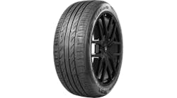
Try pushing an unforgiving rock of a tire onto a large, delicate and expensive alloy wheel, and you´ll begin to appreciate the difficulties involved in mounting today´s 45-, 40-, 35- and 30-series performance tires. The short and stiff sidewalls featured on these lowest of low-profile rubbers require specific techniques and equipment for successful mounting.
Due to the minimal compliance of many of these tires, "slipping" the beads over the rim of a mammoth-diameter, finely finished alloy wheel is anything but simple and straightforward. One "oops" with the tire iron, or one hiccup of an outdated changer machine can turn the expensive aluminum wheel into a poster child for the scrap metal industry.
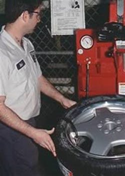
To get a first-hand look at mounting one of these rubber band-like low-profile tires, we visited Mueller Tire & Brake´s Hudson, Ohio, store location and mounted a 275/35ZR18 tire onto an 18x8.5-inch alloy rim.
In terms of selecting a changer for this type of job, bear in mind that we´re dealing with potentially high forces in terms of forcing the bead over the rim. In order to complete the task successfully and to avoid rim damage, the changer must provide a positive anchoring system that reduces the risk of rim damage. Some older style rim-clamp machines with overhead swing arms may not be up to the job, since the vertical drop-arm may deflect and jam its bead guide into the rim as the machine attempts to force the stiff bead over the rim. This can result in scraping -- or breaking -- the wheel rim, and can add a good deal of frustration to the process.
We´re not trying to promote one machine over another, although for purposes of this article, we used Mueller´s Hunter TC 3250 changer and McCourt´s MTS 2010-20 HP, a private brand tire changer made for Myers Tire Supply Co. by Corghi. These are good examples of the types of machines appropriate for this work.
In both cases, the wheel is secured to the turntable fixture via a set of expanding arms that feature rubber contact pads. Providing the pads are clean and free of contaminants, the changers will secure the wheel solidly without marking the rear inner walls of the wheel.
[PAGEBREAK]
THE PROCESS
The following step-by-step mounting instructions will give you an idea on just how careful you have to be in order to mount low-profile tires. Keep in mind, however, that the Hunter TC 3250 is the changer of record here. Some of its features differ from those of other changers, including the MTS 2010-20 HP, which clamps onto the rim from the outside in.
After checking that the changer´s expander rubber pads are clean, the wheel is placed over the spreader fixture and the spreader arms are expanded, allowing the rubber pads to securely hold the wheel in position.
With both the inboard and outboard tire beads lubricated, the rear bead is slipped over the outer rim with the aid of the machine´s bead guide. The machine´s bead guide is lowered over the tire bead, and the bead is initially slipped over the guide´s spoon. The mechanical bead pusher is then positioned downward onto the stubby sidewall.
At this point, a bead depressor tail is installed, which will prevent the tire bead from popping off of the rim as the wheel rotates clockwise.
This type of bead hold-down device is wonderful, especially when dealing with stiff-sidewall, low-profile tires that tend to otherwise jump off the rim as the wheel rotates on the machine. The bead depressor tail was designed specifically for dealing with run-flat tires and ultra-low-profile performance tires. It´s like having four or five hands and tire irons to keep the bead down during the front bead slip-over process.
The tool features a center vertical anchor that slips through the wheel hub hole and inserts into the machine´s center pad.
The first depressor clamp is attached to a horizontal sliding arm that locates the rubber clamp rigidly, providing an initial hold-down spot. As the rim rotates, the next clamp is installed, followed by the next, etc. This provides a series of anchors that prevent the tire bead from popping off the rim as the remaining tire bead is guided by the machine´s bead guide. While a clean tire iron is used as an aid, this specialty tool eliminates the need to use only irons to continue the guiding process. It´s a very slick approach, and solves the dilemma of manually forcing a stiff sidewall tire into position over the wheel rim.
Once the machine´s turntable has rotated far enough to install all of the depressor tail´s rubber clamps along the rim perimeter, the turntable only needs to rotate a few inches further in order to pop the remaining bead behind the rim. The depressor tail assembly is then removed.
This may seem like a simple procedure, and that´s exactly the point. If you have access to the correct type of equipment and specialty tools, the job is not difficult. What took a few minutes in this example could have taken hours with inappropriate tools, and the likelihood of rim damage would have been significant.
[PAGEBREAK]
MOUNTING BASICS
Keep in mind that when dealing with expensive custom wheels and high performance tires, the customer will be extremely sensitive to both cosmetics as well as performance. In order to avoid nicking, scratching or gouging a rich alloy wheel, a few basic precautionary steps must be followed.
1. Make sure the mounting machine and all specialty tools that will be used in the job are clean and free of burrs.
2. Whenever dealing with expensive alloy wheels, avoid using bare steel or iron clamping jaws, as these will easily scratch or gouge the wheel. Chances are the customer who values his high performance tires and wheels will not be pleased even if this cosmetic damage takes place on the inboard side of the wheel.
Always use rubber or plastic jaws or jaw protectors to avoid damage while clamping the wheel to the machine´s turntable. If the jaws feature rubber pads, make sure the pads are free of imbedded metal chips.
3. Always install a new valve assembly into the wheel, regardless of its apparent condition.
4. Clean the wheel´s bead seat surfaces if the wheel has been previously mounted. Remove any rubber, corrosion or grime deposits that might hinder bead sealing.
Make sure the bead lubricant is clean, and that the lube brush is free of debris.
5. Once the tire has been positioned onto the wheel, place the machine´s air hose locking-type chuck onto the valve, and stand to the side of the machine during initial seating inflation. Always wear safety glasses or goggles, and never stand directly over the tire/wheel during inflation.
6. Use a maximum of 40 psi to seat the beads. Once the beads have fully seated, remove the hose chuck and allow the air pressure to escape from the tire before inserting the valve core. Note: Check to make sure that both the inboard bead has fully seated as well. Even if the outboard bead has seated, it is still very possible that the inboard bead has not been fully positioned against the rear bead wall of the wheel.
Remember, these tires can be very stiff, and because they´re not as compliant as taller-sidewall tires, you can´t assume that both sides have popped out against their seats.
7. Always insert a new valve core, and be sure to properly snug the core into the valve. Re-inflate the tire to 40 psi. Apply a solution of clean soapy water along the bead-to-rim area to check for leaks. If bubbles are noted, this may indicate that the bead is not fully seated in that area, or that a small piece of debris is lodged between the tire and wheel. Re-inflate once again checking for leaks.
[PAGEBREAK]
MATCH MOUNTING
As a result of the manufacturing process when either wheels or tires are made, it is not uncommon to feature a very slight variation in the radial shape of either part. If the wheel and/or the tire has enough radial runout (variation from a true concentric), radial force variation can occur, wherein a "high" spot of the tire pounds the pavement during operation at speed. Bear in mind that force variation is not necessarily a weight/mass problem, but rather a radial shape problem. In other words, balancing may not cure this type of vibration. A process called "match mounting" involves finding the ideal compromise between the high spot of the tire and the low radial spot of the wheel.
By mounting the tire onto the wheel so that the wheel low spot and the tire high spot align, the potential for a radial force variation (vibration at speed) is minimized or eliminated, as the two high/low areas tend to cancel each other out.
If the tire features a color dot (indicating the high spot), this color dot may be aligned with either the wheel´s color dot (indicating the wheel low spot) or with the wheel´s air valve.
Another accurate method involves actually measuring the wheel and the tire in order to locate each component´s radial variation area. Using a Hunter GSP 9700 balancing machine as an example, the bare wheel may be mounted onto the machine´s axle shaft. A built-in electronic runout indicator is placed onto the wheel´s bead seat area.
As the wheel slowly rotates, the machine locates the wheel´s low spot. After marking this spot with chalk or a crayon, the tire is then mounted onto the wheel and spun on the machine using the built-in road wheel simulator. This applies force against the tread as the tire rotates, allowing the machine to electronically determine the mounted and inflated tire´s high spot. Once this spot is located and labeled (with chalk), the tire is then deflated, the beads are "broken" (separated from the wheel), and the tire is rotated on the wheel to align the two marks. The tire is then re-inflated, seating the tire beads. Now the assembly may be spin-balanced to correct for any weight mass bias.
This process may be time consuming, but it´s absolutely the correct method in achieving an optimized package for either the enthusiast or for correcting a nasty vibration problem that conventional balancing may not be able to solve.


