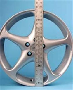
When a vehicle owner wants to dress up his or her ride with "custom" wheels, are your salespeople more than glorified order takers? If you expect to serve customers as a true wheel expert, your employees, especially the technicians, need to understand wheel dimensions.
Understanding critical dimensions such as rim diameter, rim width, offset, backspacing and bolt circle -- and being able to relate that information to the customer -- will not only help you order the correct fitment for the vehicle at hand, but also enable you to select a custom fit based on the customer´s desires.
For instance, if the customer wants to slap a set of wide honchos onto the vehicle while clearing brake or suspension components, you´ll be able to explain how that offset and backspace may need to deviate from the OE specs. And from a practical standpoint, you´ll discover any problems before you attempt to install the wrong assembled wheel.
Let´s review each critical wheel dimension in detail.
[PAGEBREAK]
WHEEL DIAMETER
Any custom wheel already should be identified -- either by a stamping in a steel wheel or by a cast-in I.D. in an alloy wheel. These usually appear on the rear of the center section or rim, but could also be found on the inside well of the rim.
For instance, a designation of "16x7" would indicate a rim diameter of 16 inches and a rim width of seven inches. But what if a size designation can´t be found, or if you want to verify the rim diameter? Here´s what you need to know.
Wheel diameter refers to the wheel´s bead seat diameter, and is not measured at the outside edge of the rim itself. Since the wheel must feature an outboard rim lip (at the front of the rim and at the back of the rim) to act as a stopping point to secure the tire bead, the outside diameter of the wheel will always be larger than the bead seat diameter. For instance, a wheel that is designed to accept a 17-inch tire may feature an outside diameter of 18.5 to 19 inches.
The wheel/rim diameter (the number that indicates tire mounting diameter) is measured at the "floor" area where the tire bead seats. It should not be confused with the overall, or outer, wheel diameter.
Since you may not own a large measuring caliper, here´s an easy method to measure wheel diameter.
First, lay the bare wheel face up or face down on a clean, flat surface. Using a straight ruler or tape measure, measure the outer diameter of the wheel, making sure that you position the ruler so that it intersects the center of the wheel. Note the outer diameter. Let´s say this is 18.5 inches.
Next, place a ruler onto the floor of the bead seat (adjacent to the side that you measured for outside diameter), with the ruler placed 90 degrees to the bead seat floor. Measure the depth from the bead seat floor to the edge of the wheel´s rim lip. Let´s say this is 3/4-inch (or 0.750 inch).
In order to determine the bead seat diameter, we need to subtract the total height of the rim lip area from the outer wheel diameter. So measure the rim lip height from each edge of the wheel (at the two spots you used when you measured overall diameter) and multiply by two. When you subtract the total height of the rim lip area from the outer wheel diameter, you get the rim, or bead seat, diameter.
Example:
Outer wheel diameter (at largest area) = 18.5"
Rim lip height is 0.750" x 2 = 1.5"
18.5" - 1.5" = 17"
In this example, the actual rim diameter where the tire seat is 17 inches, which is correct for a 17-inch tire (for example, a 225/45R17).
[PAGEBREAK]
RIM WIDTH
In order to measure wheel width, we again need to measure the area between the bead seat walls. The overall width of the wheel will vary depending on rim material thickness. For example, if a particular tire is recommended to mount to a seven-inch wide rim, the seven-inch dimension does not indicate overall wheel width, but rather the distance between the rim´s bead seat lips (where the tire bead actually makes contact).
With the bare wheel positioned upright on a clean, level surface, measure the distance from the front rim´s inner lip flange to the rear rim´s inner lip flange. For instance, a wheel that is designed with a seven-inch rim width may actually measure eight inches from the front rim face to the rear rim face.
Remember that we only want the width between the bead seat flanges. When identifying rim width, the overall width of the wheel (outside to outside) is immaterial.
When selecting a tire and wheel combination, always refer to the tiremaker´s specifications regarding recommended rim width for a particular tire. If a tiremaker notes that a 235/45R17 tire´s acceptable rim width range is "7.5-9 inches," don´t deviate. If you mount that tire onto a seven-inch-wide rim, the beads will be squeezed together beyond the tire design spec, making it difficult to mount the tire and posing an increased chance for bead damage during mounting. The tight fit also may cause the tread/shoulder area to deform, which may lead to increased wear at the center tread area in addition to potentially decreasing the tire´s design performance.
By the same token, if you attempt to mount that same tire onto a 10-inch-wide rim, you´ll run into bead seating difficulties and possible bead damage during mounting. In addition, you run the risk of increasing shoulder wear and losing some of the tire´s performance potential due to the carcass deformation on a too-wide rim.
In our example, if you have to mount a 235/45R17 tire that requires a 7.5-9-inch rim, then you´ll simply need to find a wheel that offers that recommended rim width. There is no room for debate here, even if it means moving to a different brand or style from the original brand/style the customer may have selected.
In summary, always stick to the tiremaker´s rim width recommendations. This is especially important when dealing with low profile, stiff-sidewall performance tires that don´t like being stretched or squeezed into an unnatural shape.
[PAGEBREAK]
BACKSPACE
Backspace refers to the depth of the rear of the wheel, measured from the rear of the wheel rim outer edge to the hub mounting face.
To measure, simply lay the wheel face down on a clean, level surface. Position a ruler vertically onto the hub face. Lay a long straightedge horizontally across the outer edges of the rear rim. The point where the horizontal straightedge intersects with the vertical ruler is the backspace distance (measure this on the vertical ruler that contacts the hub face).
Be sure to reference the section of your vertical ruler where it touches the underside of the horizontal straightedge. Remember, you´re trying to measure the distance from the hub face to the rear outer edge of the rim.
OFFSET
Wheel offset simply refers to the location of the wheel´s mounting surface (where the wheel mates to the hub) in relation to the centerline of the overall wheel width. If the center of the overall wheel width aligns with the hub contact surface, the wheel has zero offset. If the hub mounting face is positioned closer to the rear wheel rim, the wheel features negative offset. If the hub contact face is positioned closer to the front of the wheel rim, the wheel has positive offset.
A negative offset wheel features more rim area shoved outboard, giving it a "deep-dish" appearance because it moves the tire further outward in the wheel well.
A positive offset wheel moves the tire center further inboard (there is less rim depth at the wheel face). Front-wheel-drive applications typically require a positive offset due to the placement of the vehicle hub.
The offset dimension is critical for a number of reasons, including outboard (fender) and inboard (suspension/brake) clearance, as well as handling and braking performance. Excessive negative offset can increase the loads experienced by wheel bearings and ball joints due to an extended leverage effect.
Too much negative offset will increase the front axle track width, which would increase steering wheel effort and steering wheel "kickback."
In the majority of cases, it´s always best to adhere to the OE wheel offset as close as possible. However, it´s feasible to deviate offset by as much as 5mm; in some cases, increasing or decreasing offset by as much as 8mm or so may be acceptable. For example, if clearance isn´t a problem (it´s always best to measure first for clearance), increasing the OE offset from +35mm to +40mm should pose no problems.
If rim width is altered from OE (most performance enthusiasts tend to move to a wider wheel/tire package), offset likely will change in order to maintain proper inboard and outboard clearances. Always be aware that offset affects not only appearance, but also handling, straight-line tracking and steering effort. The rule of thumb: Always maintain offset as close to OE as possible.
Measuring offset -- the difference between the wheel´s hub face location and the center of the rim width -- is fairly simple. Refer to the backspace measurement taken earlier, and mark this on the rim´s drop-center well surface (this dimension represents the distance from the wheel rim´s rear outer edge to the hub mounting face).
Next, place a mark on the rim´s center well area that represents the center point between the wheel´s front and rear rim faces (total wheel width). The difference between these two marks represents offset.
If the hub face is positioned behind the rim center (toward the wheel back), the wheel features negative offset. If the hub face is located forward of the rim center (toward the front of the wheel), the wheel has positive offset.
Example of negative offset:
Overall wheel width = 8"
Backspace = 3.5"
3.5 - (8 divided by 2) = 3.5 - 4 = -.5"
In this example, the wheel features a negative 1/2-inch offset.
Example of positive offset:
Overall wheel width = 8"
Backspace = 4.5"
4.5 - (8 divided by 2) = 4.5 - 4 = +.5"
In this example, the wheel features a positive 1/2-inch offset)
[PAGEBREAK]
INCHES VS. MILLIMETERS
If you´re considering wheels that are identified by the maker in millimeters, you´ll need to either use a metric ruler during your measurements, or convert inches to millimeters. One inch equals 25.4 millimeters.
In order to convert inches to millimeters, multiply inches by 25.4. For example, four inches multiplied by 25.4 equals 101.6mm. In order to convert millimeters to inches, divide millimeters by 25.4.
BOLT CIRCLE
The "bolt circle" refers to the spacing of the wheel´s fastener holes, using a diameter, or circle, as the measurement. If we draw a circular line that runs through the center of all of the bolt holes, this circular diameter measurement indicates the bolt circle.
For instance, if a 4.5-inch circle can be positioned at the center of the bolt hole group, this is a "4.5-inch bolt circle." If the circle measures 100mm, it´s a 100mm bolt circle, etc.
The bolt pattern refers to both the number of fastener locations and the diameter of the hole pattern. A 5 x 100 bolt pattern refers to a wheel that features five fastener holes laid out in a 100mm diameter path. A 5 x 4.75 pattern designation refers to a pattern with five holes running along a 4.75-inch diameter. In the "old" days, we could generically refer to a 5 x 4.5-inch pattern as a "Ford" pattern, or a 5 x 4.75-inch as a "Chevy" pattern. Aside from dealing with vintage domestics, those days are gone.
In order to measure bolt circle using a ruler, remember that we´re simply trying to find the diameter of an imaginary circle that runs through the center of each fastener hole. If the wheel or hub features directly opposing holes (as found on a four-bolt, six-bolt or eight-bolt wheel or hub), simply measure from the center of one hole to the center of the hole directly across the pattern (or from the outside of one hole to the inside of the opposite hole).
If the wheel or hub features a five-bolt pattern, measure from the center of one hole to the outside edge of the hole furthest away.
If you don´t wish to be bothered by measuring with a ruler, tape measure or dial caliper, you can cheat by using a specialty measuring device. Round plastic bolt circle template discs are available that feature multiple hole patterns (with each hole identified for bolt circle). Simply place the disc against a wheel hub face or onto the vehicle hub until all holes align. The holes that align to your wheel or hub indicate the bolt circle (again, the holes are labeled).
Another specialty tool that allows quick measuring of a wheel´s bolt circle is in the form of a sliding caliper. This tool features two tapered dowels that slip into the wheel´s bolt holes. With this specific tool, insert the dowels into two adjacent holes (two holes closest together). The graduated gauge face of the tool indicates the bolt circle, based on the number of bolt holes (the gauge features multiple pointers for four-bolt, five-bolt, six-bolt or eight-bolt patterns).
While these tools are available from a number of sources, we´ll name two as examples. The round bolt circle template discs are offered by Made for You Products, while the sliding caliper tool is offered by Excalibur Wheel Accessories We sourced both tools through American Tire Distributors.
Some common fractional bolt circles include 4.00 inch, 4.25 inch, 4.50 inch and 4.75 inch (and larger on some trucks and SUVs).
Some common metric bolt circles include 100mm, 110mm, 114mm, 115mm, 120mm, 130mm and 140mm. Other circle sizes also may be used in some applications.
[PAGEBREAK]
DETERMINING FASTENER SIZES
All too often, wheel fasteners are treated as mere afterthoughts, when in fact they´re one of the most critical components on any vehicle. Wheel fasteners provide the only means of attaching the wheel/tire package onto the vehicle, whether that involves nuts threading onto hub studs or bolts threading into hubs. If wheel fasteners loosen or come depart, the wheel and tires will fall off of the vehicle while it´s being driven down the highway.
Here are the basics of how to identify various nut, stud and wheel bolt sizes.
1. Fractional pitch. The pitch number refers to the number of threads found in one inch of that fastener´s length. For example, a 1/2-inch x 20 bolt would be a 1/2-inch diameter with 20 threads per inch of the bolt length (1/2-inch USS coarse would have 13 threads per inch). A 9/16-inch x 18 would be a 9/16 inches diameter with 18 threads per inch (9/16-inch USS coarse would have 12 threads per inch).
When dealing with fractional fasteners, the higher the pitch number, the finer the threads. Common fractional-sized wheel fasteners include 7/16-inch x 20, 1/2-inch x 20 and 9/16-inch x 18.
2. Metric pitch. The pitch number refers to the distance between threads (a 1.25 thread features threads spaced 1.25mm apart). It´s just too difficult to measure the small distance between two individual threads, so it also can be determined by the number of threads within a 10mm length, divided by 10. For example, if a bolt has eight threads within a 10mm length, it´s a 1.25 pitch.
When dealing with metric fasteners, the lower the pitch number, the finer the threads. If you want to look at metric fasteners in a "fine to coarse" manner, 0.75 pitch would be very fine, with pitch numbers running up the scale (1.0, 1.25, 1.5, 1.75, etc.) toward more "coarse" thread. Most metric wheel fasteners will feature a 1.25 or 1.5 pitch.
Considering that most metric wheel studs or bolts will feature a diameter of 12mm to 14mm, a 1.5 pitch would be considered relatively "fine" to "medium" (once again, pitch "fineness" is relative to shank diameter). Common metric-sized wheel fasteners include 10mm x 1.25, 12mm x 1.25, 12mm x 1.5, 12mm x 1.75, 14mm x 1.5 and 14mm x 2.0.
YOU DO THE MATH
The formula for determining rim, or bead seat, diameter is as follows:
Overall wheel diameter - (bead seat height x 2) = rim diameter
The formula for determining backspace distance and whether it´s positive or negative is as follows:
Backspace - (wheel overall width/2) = offset
WORDS TO WORK BY: Quick-reference wheel dimension definitions
Wheel diameter: diameter of the bead seat area of the rim (not measured at the overall rim diameter).
Rim width: width measured from the front bead seat wall to the rear bead seat wall. Not measured at the overall wheel width.
Backspace: Distance from the wheel hub mounting face to the rear outer edge of the rim.
Offset: the difference between the true center of the rim width to the location of the hub mounting face. If offset pushes the tire outward relative to the hub face (deep-dish appearance on the outside), this is negative offset. If offset locates the tire inboard relative to the hub face, this is positive offset.
Bolt pattern: This identifies the number of fastener holes along with the diameter path of the hole placement. A 5 x 100 bolt pattern indicates five mounting holes, with hole centers oriented along a 100mm diameter.


