DESCRIPTION AND OPERATION
The tire pressure monitor system (TPMS) warns the driver when a significant loss of tire pressure occurs in any of the equipped tires. It allows the driver to display the individual tire pressures and their locations on the driver information center. The Tire Fill Alert (TFA) (if equipped) feature provides visual and audible alerts (light flashes and horn chirps) to drivers to assist in inflating an underinflated tire to the recommended tire pressure without the need to check a gauge or the instrument panel. TFA only functions once the tire pressure is low enough to trigger the telltale on the dashboard. When the driver starts filling the underinflated tire, the corner lamp nearest to that tire will begin to flash. When the recommended pressure is reached, the horn sounds once and the turn signal lamps will stop flashing and briefly turn solid. If the tire is overinflated by more than 5 psi, the horn will sound multiple times and the turn signal lamp will continue to flash for several seconds after filling stops. To release and correct the pressure, while the turn signal lamp is still flashing, briefly press the center of the valve stem. When the recommended pressure is reached, the horn sounds once. Software Auto-location (SAL) (if equipped) is achieved by correlating information from the sensor with information from the ABS system to make a location decision. Factors such as rolling radius, steering angle, etc. cause each vehicle wheel to rotate at a unique speed and differences in tire speeds help the software auto learn feature to assign sensor IDs to the correct locations. If a new sensor has been installed or tire rotated, the vehicle must be stationary for about 20 minutes before the system can start the process of calculating correct sensor locations. For this to happen, the vehicle will need to be driven at a speed greater than 20 km/h (12 mph) for about 10 minutes.
TIRE PRESSURE SENSOR LEARNING
Tire Pressure Sensor Learn with EL-52545 (Preferred)
The EL-52545 allows the tire pressure sensors to be learned without transmitting RF data between the tire pressure sensors and the vehicle. When using the EL-52545 each tire pressure sensor ID is learned to the EL-52545 and stored internally. The EL-52545 is then connected to the vehicle DLC using the OBD2 Interface Module, which is part of the EL-52545 kit. The stored tire pressure sensor information will then be loaded into the K9 Body Control Module. Using the EL-52545 to learn tire pressure sensors will prevent the vehicle from learning errant nearby tire pressure sensors from other vehicles in a service facility environment, especially if the tire pressure sensor batteries are low. This is the GM recommended method to learn tire pressure sensors.
1) Turn on EL-52545
2) Select RDR from the on-screen display
NOTE: Make sure the TPMS tool battery is sufficient to complete the TPMS learn process. Do not place the tool directly on the valve stem. The tool should be placed against the tire sidewall near the valve stem. The TPMS sensor learn activation procedure may have to be repeated up to three times before determining a sensor is malfunctioning.
3) If available, scan the QR code on the vehicle's tire placard or certification label. If QR is not available, select MMY from the on-screen display and manually input the vehicle information.
4) Approach the vehicle starting with the left front tire and read each tire pressure sensor information by pressing the green trigger button with the EL-52545 located near the tire valve stem. Read each tire pressure sensor in the order identified on the EL-52545 .
If any sensors display "Sensor Not Compatible" on the EL-52545 screen, you will need to first make sure compatible sensors are installed on the vehicle.
5) If any tire pressure sensors do not respond: Replace the tire pressure sensor only after several attempts have been made to identify all sensors. Undetected sensor will be identified with "No Sensor Detected" displayed in the table. After sensor replacement rerun RDR procedure. If all sensors respond, proceed to next step.
6) Verify the BAT value for each tire pressure sensor in the table on the EL-52545 is OK. If a sensor is not OK, replace the tire pressure sensor and rerun RDR procedure.
7) Verify the pressure and temperature values are reasonable based on the ambient conditions and actual tire pressure. If either value is inaccurate, replace the tire pressure sensor and rerun RDR procedure.
8) Ignition On/Vehicle in Service Mode.
9) Connect the EL-52545 OBD2 Interface Module to the EL-52545 .
10) Verify the OBDII icon is displayed on the EL-52545 and the green com LED is flashing on the EL-52545 OBD2 interface module.
11) Connect the other end of the OBD2 interface module to the vehicle DLC.
12) Select OK on the EL-52545 and follow the on-screen instructions.
Tire Pressure Sensor Learn with EL-50448 (Alternative)
When EL-50448 Tire Pressure Monitor Sensor Activation Tool is used in activate mode, it produces a low frequency transmission that activates the sensor. The sensor responds to a low frequency activation by transmitting in Learn Mode-Remotely Triggered. When the BCM receives a learn mode transmission while in learn mode, it will assign that sensor’s ID to the location on the vehicle relative to the order in which it was learned.
NOTE: In the event a particular sensor is activated and the horn does not chirp, it may be necessary to rotate the wheel so that the valve stem is in a different position due to the sensor signal being blocked by another component. Make sure the TPMS tool battery is sufficient to complete the learn process. Do not place the tool directly on the valve stem. The tool should be placed against the tire sidewall near the valve stem. The TPMS sensor learn activation procedure may have to be repeated up to three times before determining a sensor is malfunctioning.
1) Ignition On/Vehicle in Service Mode. Using driver information center buttons or scan tool (if available), initiate the Tire Pressure Sensors Learn mode. A double horn chirp will sound indicating the learn mode has been enabled. The left front turn signal will also be illuminated.
2) Starting with the left front tire, activate the sensor by holding the antenna of the tire pressure monitor activation tool aimed upward against the tire sidewall close to the wheel rim at the valve stem location. Press and release the activate button. Ensure that the transmit indicator on the special tool indicates that the sensor activation signal is being transmitted. Wait for a horn chirp. If the horn does not chirp, repeat the sensor activation sequence with the tool. Once the horn chirp has sounded, the sensor information is learned and the turn signal in the next location to be learned will illuminate.
3) After the horn chirp has sounded and the right front turn signal is illuminated, repeat the previous step for the remaining sensors in the following order: Right front/right rear/left rear.
4) When the left rear sensor has been learned and a double horn chirp has sounded, the learn process is complete and the BCM exits the learn mode.
TPMS REMOVAL AND INSTALLATION
Removal Procedure
1) Raise and support the vehicle.
2) Remove the tire and wheel assembly.
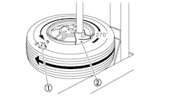
3) Demount the tire from the rim.
4) Insert an anti-rotation pin through the cross-drilled hole in the valve stem as shown in Fig. 1.
5) Hold the valve stem (3) to prevent it from rotating, then remove and discard the bolt (1) from the tire pressure indicator sensor (2), as indicated in Fig. 2.
Do not twist the tire pressure indicator sensor to remove.
6) Pull the tire pressure indicator sensor straight off the valve stem.
7) Cut the inner seal off the valve stem.
CAUTION: Do not scratch or damage the clear coating on aluminum wheels with the tire changing equipment. Scratching the clear coating could cause the aluminum wheel to corrode and the clear coating to peel from the wheel.
8) Remove and discard the valve stem by pulling it through the rim using a valve stem removal tool.
9) Clean all sealing surfaces.
Installation Procedure
NOTE: The tire pressure indicator sensor is supplied assembled to a NEW valve stem. They must be separated before installation.
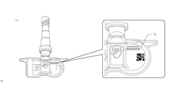
1) Remove the new bolt (3) from the tire pressure indicator sensor (2) and pull it straight off the NEW valve stem (1) as shown in Fig. 3
2) Apply lubricant to the new valve stem.
Valve stems and bolts are single use items.
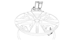
3) Using a tire pressure valve stem mounting tool, pull the valve stem through in a direction parallel to the valve hole on the rim.
Ensure the flat surfaces of the tire pressure indicator sensor and the tire pressure valve stem are located correctly.
4) Rotate the valve stem by hand to align the tire pressure indicator sensor. Do not tighten the bolt at this stage.
5) Assemble the tire pressure indicator sensor to the valve stem and install the new bolt hand tight.
6) Insert an anti-rotation pin through the cross-drilled hole in the valve stem.
7) Hold the valve stem to prevent it from rotating and tighten the bolt to 1.4 N.m (12.4 lb in).
8) As shown in Fig. 4, check the valve stem (1) to ensure that it is fully seated on the rim (2) as follows:
- The rim hole edge has to be completely in the notch of the valve stem.
- The valve and the rim hole have to be concentric.
9) Make sure that there is a parallel gap between the valve stem (1) and the tire pressure indicator sensor (2) as shown in Fig. 5.
NOTE: The tire pressure indicator sensor must not be in contact with the wheel.
10) When correctly positioned there will be a parallel gap between the tire pressure indicator sensor and the wheel, indicated in Fig. 6.
NOTE:
- Tire pressure indicator sensors are shipped in the OFF mode. The sensor will exit its OFF state when the tire is inflated.
- The tire should not have contact with the tire pressure indicator sensor during installation to prevent damage to the tire pressure indicator sensor.
11) Mount the tire to the wheel.
12) Install the tire and wheel assembly.
13) Remove the support and lower the vehicle.
14) Perform the tire pressure indicator sensor learn procedure.
TORQUE SPECIFICATIONS
Application Specification
Metric (English)
Tire Pressure Indicator Sensor Bolt 1.4 N.m (12.4 lb in)


