TPMS: Ford Taurus, Police Sedan and Lincoln MKS, 2011-19
SUBJECT VEHICLES: Ford Taurus 2011-19, Ford Police Interceptor Sedan 2014-19, Ford Special Service Police Sedan 2015-17, and Lincoln MKS 2011-16.
SPECIAL TOOLS NEEDED? Yes, a TPMS activation tool (204-363) must be used.
The tire pressure monitoring system (TPMS) monitors the air pressure in the four road tires with wheel-mounted tire pressure sensors. The sensors transmit radio frequency signals to the smart junction box (SJB) approximately every 60 seconds when the vehicle speed exceeds 20 mph (32 km/h).
If the vehicle is stationary for more than 30 minutes, the sensor will enter into a “sleep mode” and stop transmitting. Each tire pressure sensor transmission is compared against a low-pressure limit (the pressure listed on the vehicle certification label minus 25%, which will be about 6-9 psi).If it is determined that the tire pressure has fallen below this limit, the SJB sends a message to the instrument cluster, which then illuminates the low pressure warning indicator and displays the appropriate message(s) in the message center (if equipped). NOTE: The smart junction box is also known as the generic electronic module (GEM).
Under the following conditions, the TPMS may not function properly:
- Low tire pressure.
- The tire pressure sensor is missing or damaged.
- A spare tire is installed as a road wheel.
- An incorrect tire pressure sensor is installed.
- A tire pressure sensor is installed incorrectly.
- Non-OEM wheels are installed (aftermarket rims).
- Non-OEM equipped run-flat tires are installed.
- There are other non-OEM modifications (roll cages, service barriers, part racks, ladder racks, etc.).
Tire pressure monitor warning indicators
NOTE: As ambient temperature decreases by 10 degrees Fahrenheit (6 degrees Celsius), tire pressure decreases 1 psi (7 kPa). If tire pressures are not adjusted at cold temperature, the tire pressure may drop enough to be detected by the TPMS, which will activate the low pressure warning light.
When the tire pressure warning light comes on solid and the message center displays “LOW TIRE PRESSURE,” check the air pressure of all the tires and adjust to the specified cold pressure listed on the vehicle certification label (found on the driver’s door or door pillar). Drive the vehicle at 20 mph (32 km/h) for at least 2 minutes. Make sure the warning light goes off. If the warning light stays on, there is a malfunction in the TPMS. See the appropriate manufacturer service information. The TPMS warning indicator flashes for 70 seconds, then remains on continuously when the ignition is turned to the ON position if the TPMS is malfunctioning. The following messages indicate a system malfunction:
- Tire pressure sensor fault — The message center displays TIRE PRESSURE SENSOR FAULT when a TPMS sensor is malfunctioning.
- No communication with the BCM — The TPMS warning indicator illuminates when the IPC has not received any signals from the BCM for more than 5 seconds. The message center displays TIRE PRESSURE MONITOR FAULT.
- Tire pressure monitor fault — The message center displays TIRE PRESSURE MONITOR FAULT when the TPMS is malfunctioning. See the appropriate manufacturer service information.
TPMS reset procedures
NOTE: If the tire pressure sensor is replaced, it will need to be trained. Training the sensors is not necessary after a tire rotation on vehicles with the same front and rear tire pressures, but the BCM cannot recognize that the sensor identifiers have been moved to different positions, it only retains the original position the sensors were last trained to.
NOTE: Do not use the TPMS reset procedure outlined in the owner’s literature as this procedure will not program new sensors to the module.
When the tire pressure warning light comes on solid and the message center displays “LOW TIRE PRESSURE,” check the air pressure of all tires and adjust to the specified cold pressure listed on the vehicle certification label (found on the driver’s door or door pillar). Drive the vehicle at 20 mph (32 km/h) for at least 2 minutes. Make sure the warning light goes off.
Tire pressure sensor training
NOTE: In the following procedure, a TPMS activation tool (204-363) must be used.
NOTE: The tire pressure sensor training procedure must be done on a single vehicle, in an area without radio frequency (RF) noise and at least three feet away from any other vehicle equipped with a TPMS. RF noise is generated by an electrical motor and appliance operation, cellular telephones and remote transmitters, power inverters and portable entertainment equipment.
NOTE: If the vehicle has been stationary for more than 30 minutes, the sensors will go into a “sleep mode” to conserve battery power. It will be necessary to wake them up so they will transmit the latest tire pressure information to the body control module (BCM). Refer to “Tire pressure sensor activation.”
NOTE: If a sensor does not respond to the TPMS activation tool, attempt to activate the same sensor with the TPMS activation tool.
If the sensor still does not respond, move the vehicle to rotate the wheels at least one-fourth turn and attempt to activate the same sensor again.
NOTE: The body control module (BCM) has a 2-minute time limit between sensor responses. If the BCM does not recognize any 1 of the 4 tire pressure sensors during this time limit, the horn will sound twice and the message center (if equipped) will display TIRE NOT TRAINED REPEAT and the entire procedure must be repeated.
Vehicles with intelligent access (IA):
1) Set the tire pressure of all wheels to the pressure specified on the tire and loading information label.
2) Close all doors.
3) Turn the ignition switch to the OFF position, then press and release the brake pedal.
4) Using the START/STOP button, switch from the OFF to ACCESSORY to RUN position 3 times, ending in the RUN position.
5) Press and release the brake pedal.
6) Turn the ignition switch to the OFF position.
7) Using the START/STOP button, switch from the OFF to ACCESSORY to RUN position 3 times, ending in the RUN position.
NOTE: It may take up to 6 seconds to activate a tire pressure sensor. During this time, the TPMS activation tool must remain in place at the valve stem.
8) Place the TPMS activation tool on the left front tire wall at the valve stem. Press the “TEST” button. The horn will sound briefly to indicate that the tire pressure sensor has been recognized.
NOTE: Do not wait more than 2 minutes between training each sensor or the BCM will time out and the entire procedure must be repeated.
9) Within 2 minutes after the horn sounds, place the TPMS activation tool on the right front tire wall at the valve stem. Then press the test button to train the right front tire pressure sensor. Repeat this procedure for the right rear and left rear tires, in that order.
10) When the tire training procedure is complete, the message center (if equipped) will display “TIRE TRAINING COMPLETE.” For vehicles not equipped with a message center, successful completion of the training procedure will be verified by turning the ignition switch to the OFF position without the horn sounding. If the horn sounds twice when ignition is turned off, the training procedure was not successful.
Vehicles with integrated key head transmitter (IKT):
1) Set the tire pressure of all wheels to the pressure specified on the tire and loading information label.
2) Turn the ignition switch to OFF, then press and release the brake pedal.
3) Turn the ignition switch from the OFF position to the RUN position 3 times ending in the RUN position. Do not wait more than one minute between each key cycle.
4) Press and release the brake pedal.
5) Turn the ignition switch to the OFF position.
NOTE: The horn will sound once and the TPMS indicator will flash if the training mode has been entered successfully. If equipped, the message center will display TRAIN LF TIRE.
6) Turn the ignition switch from the OFF position to the RUN position 3 times, ending in the RUN position. Do not wait more than one minute between each key cycle.
NOTE: It may take up to 6 seconds to activate a tire pressure sensor. During this time, the TPMS activation tool must remain in place at the valve stem.
7) Place the TPMS activation tool on the left front tire wall at the valve stem. Press the “TEST” button. The horn will sound briefly to indicate that the tire pressure sensor has been recognized by the DDM.
NOTE: Do not wait more than 2 minutes between training each sensor or the BCM will time out and the entire procedure must be repeated.
8) Within 2 minutes after the horn sounds, place the TPMS activation tool on the right front tire wall at the valve stem. Then press the test button to train the right front tire pressure sensor. Repeat this procedure for the right rear and left rear tires, in that order.
9) When the tire training procedure is complete, the message center (if equipped) will display “TIRE TRAINING COMPLETE.” For vehicles not equipped with a message center, successful completion of the training procedure will be verified by turning the ignition switch to the OFF position without the horn sounding. If the horn sounds twice when the ignition is turned off, the training procedure was not successful.
Tire pressure sensor activation
NOTE: The tire pressure sensors will go into a “sleep mode” when a vehicle is stationary to conserve battery power. The sensors do not transmit information while in sleep mode. It will be necessary to wake them up so they will transmit the latest tire pressure information.
1) Turn the ignition switch to ON.
2) Position the TPMS activation tool against the left front (LF) tire sidewall at the tire valve stem.
NOTE: The TPMS activation tool should provide feedback in the form of a flashing green light and a beep sound for each successful response from a tire pressure sensor. This feedback may not always be present, do not rely on it as a confirmation that the module heard a particular sensor.
NOTE: If a sensor does not respond to the TPMS activation tool, move the vehicle to rotate the wheels at least one-fourth of a turn and attempt to activate the same sensor again. If the sensor still does not respond, attempt to activate the same sensor again using the activation tool (if available). If the sensor still fails to train, attempt to train the sensor with the vehicle doors open.
3) Press the test button on the TPMS activation tool to activate the sensor. Activate the sensor at least 2 times.
4) Repeat this procedure for the 3 remaining tires.
5) If the TPMS indicator remains illuminated after adjusting and activating each sensor, see the appropriate manufacturer service information.
Demounting/mounting procedures
CAUTION: The tire should be demounted from the wheel using the tire changer manufacturer’s instructions. Use the following information to avoid damage during the demounting/mounting procedures.
Tire pressure sensor
WARNING: The TPMS sensor battery may release hazardous chemicals if exposed to extreme mechanical damage. If these chemicals contact the skin or eyes, flush immediately with water for a minimum of 15 minutes and get prompt medical attention. If any part of the battery is swallowed, contact a physician immediately.
When disposing of TPMS sensors, follow the correct procedures for hazardous material disposal. Failure to follow these instructions may result in serious personal injury.
NOTE: The TPMS sensor cannot be removed without disassembly of the wheel and tire.
Disassembly
CAUTION: Failure to follow the instructions below may result in damage to the TPMS sensor.
NOTE: The TPMS sensor is mounted to the valve stem. Removal of the valve stem requires demounting the tire from the wheel and removal of the TPMS sensor.
NOTE: Use only the TPMS activation tool any time tire pressures are measured to be sure that accurate values are obtained.
1) Remove the wheel and tire.
NOTE: The valve stem is connected to the TPMS sensor. Do not pull the valve stem from the wheel, or damage to the sensor will occur.
2) Remove the valve stem core and fully deflate all air from the tire. If a new TPMS sensor is being installed, remove and discard the valve stem-to-sensor screw and the sensor.
NOTE: Do not allow the tire beads to move beyond the wheel mid-plane (middle of the wheel) when separating the beads from the wheels, as damage to the TPMS sensor may occur.
NOTE: Tire and valve stem position is critical to prevent damage to the TPMS sensor when using a paddle-type bead separator.
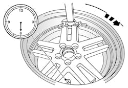
NOTE: Some machines may have a nylon roller bead separator at the 12 o’clock position instead of the paddle-type bead separator at the 3 o’clock position.
3) Position the wheel and tire assembly on a suitable tire machine and separate both beads of the tire from the wheel.
For a paddle-type tire machine, position the valve stem at the 12 o’clock or 6 o’clock position and the paddle at the 3 o’clock position.For a roller-type tire machine, align the valve stem with the roller at any position.
NOTE: Index-mark the valve stem and wheel weight positions on the tire.4) Place the wheel and tire assembly on the turntable of the tire machine with the valve stem at the 11:30 position and the machine arm at the 12 o’clock position and demount the outer bead from the wheel (see Figure 2).
5) Reset the wheel and tire assembly on the turntable of the tire machine with the valve stem at the 11:30 position and the machine arm at the 12 o’clock position and demount the inner bead from the wheel.
NOTE: A new valve s tem must be installed whenever a new tire or wheel is installed.
NOTE: When installing a new wheel, always install a new valve stem and sensor screw. Reuse the TPMS sensor from the previous wheel if possible. The TPMS will not have to be trained if the sensor is reused.6) Remove the TPMS sensor in the following sequence.
a) Using a T10 Torx, remove the valve stem-to-TPMS sensor screw.
b) Carefully and firmly, pull the sensor straight down and separate it from the valve stem (see Figure 3).
NOTE: Use care not to damage the wheel surface when removing the valve stem.
c) Using a suitable valve stem puller and a wood block, remove the valve stem from the wheel (see Figure 4).
d) If the TPMS sensor is being reused, inspect the TPMS sensor for damage and install a new sensor as necessary.
Assembly
CAUTION: Damage to the TPMS sensor may result if the tire mounting is not carried out as instructed.CAUTION: To prevent TPMS sensor and valve stem damage, the valve stem must be installed onto the TPMS sensor and then installed into the wheel as an assembly.1) Install a new valve stem onto the TPMS sensor. Tighten the new valve stem-to-TPMS sensor screw to 13 in.-lbs. (2 Nm) — (see Figure 5).
NOTE: Use care not to damage the wheel surface when installing the valve stem and TPMS sensor assembly.
NOTE: It is important to pull the valve stem and TPMS sensor assembly through the wheel rim hole in a direction parallel to the valve stem hole axis. If the assembly is pulled through at an angle, damage to the valve stem and sensor assembly may occur.
2) Lubricate the valve stem with soapy water and install the valve stem and TPMS sensor assembly into the wheel using a block of wood and a suitable valve stem installer (see Figure 6).3) Make sure the valve stem rubber is fully seated against the wheel (see Figure 7).
NOTE: Do not mount the tire at this time.
NOTE: Lubricate the tire beads using a suitable fast-drying, corrosion-inhibiting tire bead lubricant.
4) Position the wheel on the turntable of the tire machine, and then lubricate and position the bottom bead of the tire on the wheel.
5) Position the wheel to align the valve stem with the machine arm, at the 6 o’clock position, and mount the bottom bead of the tire (see Figure 8).6) Reposition the wheel to align the valve stem with the machine arm at the 6 o’clock position, and mount the top bead of the tire.
NOTE: Use only the TPMS activation tool any time tire pressures are measured to make sure that accurate values are obtained.
7) Inflate the tire to the pressure specified on the vehicle verification (VC) label located on the driver door or door pillar. Proceed to Step 8 if the tire beads do not seat at the specified inflation pressure.
WARNING: If there is a need to exceed the maximum pressure indicated on the sidewall of the tire, in order to seat the beads, follow all the steps listed below. Failure to follow these steps may result in serious personal injury.CAUTION: Do not exceed 276 kPa (40.03 psi) above the maximum pressure on tire sidewall. Install a new tire if the beads do not seat at this pressure.
8) The following steps should only be carried out if the tire beads cannot be seated by inflating the tire up to the maximum inflation pressure listed on the tire sidewall.
a) Relubricate the tire bead and wheel bead seat area.
b) Install a remote valve and pressure gauge.
c) Wear eye and ear protection and stand at a minimum of 3.65 m (11.98 ft.) away from the wheel and tire assembly.
d) Inflate the tire using the remote valve and tire gauge until the beads have seated or until the pressure gauge is 138 kPa (20.01 psi) more than maximum inflation pressure on tire sidewall. If beads have not seated, deflate the tire and proceed to the next step.
e) Place the wheel and tire assembly in an Occupational Safety and Health Administration (OSHA)-approved tire safety cage. f) Inflate the tire using the remote valve and pressure gauge until the beads have seated or until the pressure gauge is 276 kPa (40.03 psi) more than maximum inflation pressure on the tire sidewall.
9) Install the wheel and tire.
10) The tire pressure sensor will need to be trained. See “Tire pressure sensor training.” ■