DESCRIPTION & OPERATION
The BCM uses tire pressure sensors to monitor tire pressure. In vehicles without keyless entry and push button start, the sensors use radio signals to transmit the tire pressure to the BCM. (In vehicles with keyless entry and push button start, the sensors use radio signals to transmit the tire pressure to the RTM. The RTM sends the information to the BCM over a LIN.) The tire pressure sensors are battery operated and mounted to the valve stems. The IPC illuminates the TPMS warning indicator and the message center displays a message when a fault is present or when the tire pressure falls below the low pressure limit.
OPERATION & COMPONENT DESCRIPTION
TPMS Function: When directed to train any TPMS sensors, use only the sensor training procedure outlined in this article. Do not use the TPMS reset procedure outlined in the Owner's Literature as this procedure does not program new sensors to the module.
The TPMS uses four valve stem mounted sensors to monitor tire pressure. These sensors wirelessly transmit tire pressure data to the BCM. All TPMS functions are controlled by the BCM. The BCM compares the tire pressure data with a programmed tire pressure. This programmed pressure is specified on the VC label and cannot be changed. If the actual tire pressure is less than the programmed tire pressure, the BCM sends a low tire pressure message to the GWM along the HS-CAN1. The GWM then sends this message to the IPC along the HS-CAN3. The IPC responds by illuminating the TPMS warning indicator and displaying a low tire pressure message in the message center.
The TPMS sensors are trained (calibrated) to the BCM which records the unique identifier for each sensor and records the location of each sensor based on the training (calibration) order. The BCM sends messages to the IPC by first sending the information along the HS-CAN1 to the GWM which then sends the information to the IPC along the HS-CAN3. The diagnostic scan tool is useful in diagnosing TPMS concerns and may be used to verify the accuracy of the tire pressure data transmitted by the TPMS sensors. This is accomplished by comparing the BCM tire pressure PID data to the actual tire pressure using a digital tire pressure gauge. It is not necessary to train the sensors after a tire rotation on vehicles with the same front and rear tire pressures however, the BCM cannot recognize the sensor identifiers have been moved to different positions and retains the original position information for each sensor.
Wheel Rotation and Sensor Training Techniques: Training known good sensors from another vehicle can help determine whether the concern is with a sensor or the BCM. This technique cannot help determine whether the concern is due to RFI as some RFI source could be preventing the BCM from receiving the tire pressure status from the known good sensors as well as the original sensors. If the BCM in the suspect vehicle cannot train any of the original sensors and, likewise, cannot train known good sensors from another vehicle, then the concern is with the module or RFI and not with the original sensors. The original sensors should not be replaced. If a sensor in a certain location has caused several events, yet the sensor trains and seems to operate normally, moving that particular wheel to a different location on the vehicle is a good way to isolate the concern to a certain sensor/wheel location. Rotate the wheels and road test the vehicle. This can be done in an attempt to replicate the concern and help determine if the concern followed the sensor or remained in the original sensor location. If the vehicle has been stationary for more than 30 minutes, the sensors go into a "sleep mode" to conserve battery power and need to be "woken up" so they transmit the latest tire pressure information to the BCM.
Training Sensors in a Different Order: If the first sensor fails the TPMS training procedure, the BCM aborts the entire procedure. Starting the training procedure at a different wheel can determine if the remaining sensors can train to the module. This can help save time determining if one sensor is damaged, other sensors are having concerns or the BCM is experiencing training difficulties with a certain TPMS sensor location.
Ambient Temperature Change and Tire Pressure: Tire pressures fluctuate with temperature changes. For this reason, tire pressures must be set to specification when tires are at outdoor ambient temperatures. If the vehicle is allowed to warm up to shop temperatures, and the outside temperature is less than shop temperature, the tire inflation pressure must be adjusted accordingly. If the tires are inflated to specification at shop temperatures, and the vehicle is moved outdoors when the outdoor ambient temperature is significantly lower, the tire pressure may lower enough to be detected by the TPMS sensor and activate the TPMS warning indicator. As the ambient temperature decreases by 10 degrees Fahrenheit, tire pressure decreases 1 psi. Adjust the tire pressure as necessary to keep the tire at the specified VC label pressure. To adjust the tire pressure indoors for colder outside temperatures, refer to the following example table.
BCM Description: The BCM is a multifunction module that monitors all sensor inputs and all CAN messages that relate to the TPMS. The BCM records and retains the unique sensor identifier of each TPMS sensor. The BCM retains the previous sensor location information following a tire rotation. For the BCM to learn the new sensor location, the sensors must be trained (calibrated) to the BCM. Additionally, the sensors must be trained when a new BCM is installed. When installing a new BCM, there are several procedures that must be carried out in order for the module to function correctly. These procedures include, but are not limited to: PMI, anti-theft parameter reset, programming keyless entry remote and setting customer preferences.
All four TPMS sensors must be trained when a new BCM is installed. TPMS pressure data is cleared from the BCM when the module is flashed or reconfigured. When the data is cleared, the tire pressure DID's reset to the factory default of 149.96 psi and the IPC displays dashes for the tire pressures. The sensors must be activated to transmit the latest tire pressure information.
TPMS Sensor: Each of the four TPMS sensors contain a battery, a tire pressure sensor and a radio transmitter. The TPMS sensor radio transmissions are sent approximately once every 60 seconds when the vehicle speed exceeds 20 mph.
GENERAL PROCEDURES
TPMS Sensor Activation
1. Turn the ignition switch to the on position.
2. Position the special tool against the Left Front (LF) tire sidewall at the tire valve stem.
3. Press the test button on the special tool to activate the sensor. Activate the sensor at least twice.
4. Repeat the previous two steps for the remaining tires.
TPMS SENSOR LOCATION CALIBRATION
Programming/Enter Training Mode With Scan Tool
The TPMS can be placed into learn mode using a diagnostic scan tool, or manually when a diagnostic scan tool is not available.
The horn will sound once and the TPMS indicator will flash if the training mode has been entered successfully. If equipped, the message center will display TRAIN Left Front (LF) TIRE.
1. Enter Training Mode With IDS Scan Tool: Select Chassis > Select TPMS > Select Training Mode.
2. Enter Training Mode With FDRS Scan Tool: Select Toolbox > Select BCM > Select BCM -- TPMS Initialization.
Programming / Enter Training Mode Without Scan Tool
The horn will sound once and the TPMS indicator will flash if the training mode has been entered successfully. If equipped, the message center will display TRAIN Left Front (LF) TIRE.
1. With the ignition OFF, press and release the brake pedal.
2. Using the start/stop switch, position the ignition from OFF to RUN three times, ending in the RUN position.
3. Press and release the brake pedal.
4. Position the ignition to OFF position.
5. Using the start/stop switch, position the ignition from OFF to RUN three times, ending in the RUN position.
Programming
TPMS Sensor Training Procedure
It may take up to six seconds to activate a tire pressure sensor. During this time, the special tool must remain in place at the valve stem.
1. Place the special tool on the Left Front (LF) tire sidewall at the valve stem. Press and release the test button on the special tool. The horn will sound briefly to indicate that the tire pressure sensor has been recognized by the BCM.
2. Within two minutes of the horn sounding, place the special tool on the Right Front (RF) tire sidewall at the valve stem and press and release the test button to train the Right Front (RF) tire pressure sensor.
3. Repeat the first step for the Right Rear (RR) and Left Rear (LR) tires. The procedure is completed after the last tire has been trained. When the training procedure is complete, the message center (if equipped) will display TIRE TRAINING COMPLETE. For vehicles not equipped with a message center, successful completion of the training procedure will be verified by positioning the ignition to OFF without the horn sounding. If the horn sounds twice when the ignition is positioned to OFF, the training procedure was not successful.
4. Using the scan tool, locate the updated TPMS sensor identifiers trained to the BCM and document them on the applicable warranty claim.
NOTE: This step is required to clear DTC B1182:55, cause the BCM to exit the manufacturing mode and to make sure there are no other concerns with a newly programmed BCM.
5. If the sensors are being trained due to the installation of a new BCM, clear any DTC and carry out the BCM On-Demand Self Test.
TIRE PRESSURE SENSOR REMOVAL AND INSTALLATION
DISASSEMBLY
Failure to follow the instructions below may result in damage to the TPMS.
The TPMS sensor is mounted to the valve stem. Removal of the valve stem requires demounting the tire from the wheel and removal of the TPMS sensor. Use only the Digital Tire Pressure Gauge any time tire pressures are measured to be sure that accurate values are obtained.
1. Remove the wheel and tire.
The valve stem is connected to the TPMS sensor. Do not pull the valve stem from the wheel, or damage to the sensor will occur. If a new TPMS sensor is being installed, remove and discard the valve stem-to-sensor screw and the sensor.
2. Remove the valve stem core and fully deflate all air from the tire.
Do not allow the tire beads to move beyond the wheel mid-plane (middle of the wheel) when separating the beads from the wheels; damage to the TPMS sensor may occur.
Tire and valve stem position is critical to prevent damage to the TPMS sensor when using a paddle-type bead separator.
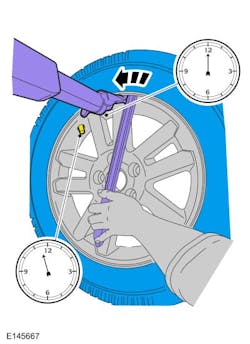
Some machines may have a nylon roller bead separator at the 12 o'clock position instead of the paddle-type bead separator at the 3 o'clock position. (Paddle type shownin Fig. 1.)
3. For a paddle-type tire machine, position the valve stem at the 12 o'clock or 6 o'clock position and the paddle at the 3 o'clock position.
For a roller-type tire machine, align the valve stem with the roller at any position.
If bead separation is difficult to achieve using the nylon roller bead separators due to high anchoring force between the tire and the wheel; the paddle-type bead separator may be a more effective method.
4. Place the wheel and tire assembly on the turntable of the tire machine with the valve stem at the 11:30 position and the machine arm at the 12 o'clock position and demount the outer bead from the wheel.
Index-mark the valve stem and wheel weight positions on the tire.
5. Reset the wheel and tire assembly on the turntable of the tire machine with the valve stem at the 11:30 position and the machine arm at the 12 o'clock position and dismount the inner bead from the wheel.
6. Remove and discard the TPMS sensor-to-valve stem screw. Separate the TPMS sensor from the valve stem. A new valve stem must be installed whenever a new tire or wheel is installed.
7. Discard the specified component. Follow local disposal regulations. Use the General Equipment: Wooden Block.
Use care not to damage the wheel surface when removing the valve stem.
When installing a new wheel, always install a new valve stem and sensor screw. Reuse the TPMS sensor from the previous wheel if possible. The TPMS will not have to be trained if the sensor is reused. If the TPMS sensor is being reused, inspect the TPMS sensor for damage and install a new sensor as necessary.
8. Position the new valve stem onto the TPMS sensor and install the new screw.
To prevent TPMS sensor and valve stem damage, the valve stem must be installed onto the TPMS sensor and then installed into the wheel as an assembly.
ASSEMBLY
Damage to the TPMS sensor may result if the tire mounting is not carried out as instructed.
1. Use the General Equipment: Wooden Block.
It is important to pull the valve stem and TPMS sensor assembly through the wheel rim hole in a direction parallel to the valve stem hole axis. If the assembly is pulled through at an angle, damage to the valve stem and sensor assembly may occur. Use care not to damage the wheel surface when installing the valve stem and TPMS sensor assembly.
Lubricate the valve stem with soapy water and install the valve stem and TPMS sensor assembly into the wheel using a block of wood and a suitable valve stem installer.
2. Position the wheel on the turntable of the tire machine, then lubricate and position the bottom bead of the tire on the wheel.
Lubricate the tire beads using a suitable fast-drying, corrosion-inhibiting tire bead lubricant. Do not mount the tire at this time.
3. Position the wheel to align the valve stem with the machine arm, at the 6 o'clock position, and mount the bottom bead of the tire.
4. Reposition the wheel to align the valve stem with the machine arm at the 6 o'clock position, and mount the top bead of the tire.
Use only the Digital Tire Pressure Gauge any time tire pressures are measured to be sure that accurate values are obtained.
Proceed to the next step if the tire beads do not seat at the specified inflation pressure.
5. Inflate the tire to the pressure specified on the VC label located on the driver door or door pillar.
If there is a need to exceed the maximum pressure indicated on the sidewall of the tire in order to seat the beads, follow all steps listed below. Failure to follow these steps may result in serious personal injury.
6. The following steps should only be carried out if the tire beads cannot be seated by inflating the tire up to the maximum inflation pressure listed on the tire sidewall.
- Relubricate the tire bead and wheel bead seat area.
- Install a remote valve and pressure gauge.
- Wear eye and ear protection and stand at a minimum of 12 feet away from the wheel and tire assembly.
- Inflate the tire using the remote valve and tire gauge until the beads have seated or until the pressure gauge is 20 psi more than maximum inflation pressure on tire sidewall. If beads have not seated, deflate the tire and proceed to the next step.
- Place the wheel and tire assembly in an OSHA-approved tire safety cage.
- Inflate the tire using the remote valve and pressure gauge until the beads have seated or until the pressure gauge is 40 psi more than maximum inflation pressure on the tire sidewall. Do not exceed 40 psi above the maximum pressure on tire sidewall. Install a new tire if the beads do not seat at this pressure.
- Install the wheel and tire.
About the Author
Mitchell 1
Information for this column comes from the tire pressure monitoring systems data in ProDemand, Mitchell 1's auto repair information software for domestic and import vehicles. Headquartered in San Diego, Mitchell 1 has provided quality repair information solutions to the automotive industry since 1918. For more information, visit www.mitchell1.com.