The tire pressure monitoring system (TPMS) in 2008-2016 Chrysler Town & Country vehicles monitors air pressure in the four road tires (excludes the spare). Pressure in the spare tire is not monitored. There are two tire pressure monitoring systems available, a base system and a premium system. The base system does not specify how many tires are low or where they are located. The premium system does so.
The base TPMS consists of tire pressure monitoring sensors attached to each road wheel through the valve stem mounting hole, a central receiver module wireless ignition node (WIN), and an indicator lamp. The premium TPMS consists of tire pressure monitoring sensors attached to each road wheel through the valve stem mounting hole, a wireless control module, three wheel sensor transponders located in three of the four wheel wells, an electronic display, and an indicator lamp.
Using an RF signal, each sensor transmits tire pressure data approximately once every minute. Each sensor’s (transmitter) broadcast is uniquely coded so that the sentry key remote entry module (SKREEM) can monitor the state of each of the sensors on the four rotating road wheels. Upon detection of a warning or fault condition, the WIN will send a request to the module that controls the indicator lamp (and the text display if equipped with the premium system) via the vehicle bus system to illuminate or flash the indicator lamp. Also, upon detection of a warning or fault condition, the electronic display will send a request to sound the “chime.”
The WIN will store all warning and fault conditions, placard pressure values and low-pressure threshold values (lamp ON and OFF) in memory that can be accessed through diagnostic communication. If new sensors are introduced to the vehicle, the data stored for the sensor being replaced will be deleted. The WIN will store all wheel sensor IDs and locations and faults in memory that can be accessed through diagnostic communication. All other data values transmitted from each active wheel sensor (not the spare tire) shall be stored in the WIN memory.
After a sensor has been replaced, the WIN automatically learns and stores the sensor IDs while driving continuously above 15 mph (24 km/h) for 10 minutes. The learning sequence will initiate when the vehicle has been stopped for more than 20 minutes. Under the following conditions, the system may not function properly:
• The areas, facilities or devices that use similar radio wave frequencies are located in the vicinity of the vehicle.
• A radio device of similar frequency is used near the vehicle.
• A lot of snow or ice is stuck to the vehicle, especially around the wheels or wheel housings.
• The battery of the sensor has been depleted (approximate 10-year life span).
• A spare tire is installed.
• A tire without a tire pressure sensor is used.
• Wheels other than manufacturer factory wheels are used.
TIRE PRESSURE MONITOR WARNING INDICATORS
If the TPMS detects that the tire pressure in any road tire is going low, the TPMS will continuously illuminate an indicator lamp. In the premium TPMS, in addition to the chime and lamp, a graphic display of the pressure value(s) and position of the low tire(s) will flash in the electronic vehicle information center (EVIC). Once pressure in the suspect tire(s) raises above the low pressure (lamp) OFF threshold, and the TPMS module receives a valid transmission from the sensor, the lamp will go out.
If a system fault is detected, a chime will sound, and the TPMS indicator (telltale) lamp will flash for 75 seconds, then remain on solid. For vehicles with the premium TPMS, a “CHECK TPM SYSTEM” message will appear in the EVIC, followed by a graphic display. See the appropriate manufacturer service information.
TPMS RESET PROCEDURES
NOTE: If a tire pressure sensor has been replaced, the tire pressure sensors must be retrained. When the tire pressure warning light illuminates and warning message appears, immediately check air pressure of all tires and adjust to the specified pressure. Drive the vehicle above 15 mph (24 km/h) for a few minutes. Ensure warning indicators go out.
TIRE PRESSURE SENSOR RETRAINING
NOTE: The vehicle must be stationary for more than 20 minutes in order to initiate the learning sequence.
Automatic sensor training
The SKREEM automatically learns and stores the sensor’s ID while driving after a sensor has been replaced. There is no formal retraining procedure necessary. Drive the vehicle for a minimum of 10 to 20 minutes while maintaining a continuous speed above 15 mph (24 km/h). During this time, the system will learn the new sensor ID code and will clear any DTCs automatically. If a sensor cannot be trained, see the appropriate manufacturer service information.
Scan tool sensor training
NOTE: A new sensor ID can also be programmed directly into the WIN or TPMS module by using an RKE-TPM Analyzer in conjunction with a scan tool. Using a TPM-RKE Analyzer can take up to a minute to force a transmission from a sensor. Once the new sensor ID has been programmed, the vehicle will need to be driven above 15 mph (24 km/h) until the fault is no longer active (lamp extinguishes) and the display is updated (10 to 20 minutes).
Scan each TPMS sensor at each road wheel, and then store each sensor ID in the correct location (left front, left rear, right front, and right rear).
Connect the TPM-RKE Analyzer tool to the scan tool. Then follow the programming steps outlined in the diagnostic scan tool for “Program Tire Pressure Sensor ID w/ TPM Tool.”
DEMOUNTING/MOUNTING PROCEDURES
CAUTION: The tire should be demounted from the wheel using the tire changer manufacturer’s instructions. Use the following information to avoid damage during the demounting/mounting procedures.
CAUTION: The TPMS has been optimized for the original equipment tires and wheels. TPMS pressures have been established for the tire size equipped on the vehicle. Undesirable system operation or sensor damage may result when using replacement equipment that is not of the same size, type, or style. Aftermarket wheels can cause sensor damage.
Do not use aftermarket tire sealants or balance beads if your vehicle is equipped with TPMS, as damage to the sensors may result. NOTE: If a tire pressure sensor has been replaced, the tire pressure sensors must be retrained. See “TPMS RESET PROCEDURES.”
NOTE: If the tires require leak-testing, a water test may be used to check for a leak around the sensor as long as any water at the valve core is removed when the procedure is completed. Water can be expelled from the core area by pushing in on the core for several seconds, allowing escaping air to drive out any moisture. Re-inflate the tire as necessary. Install the original valve stem cap.
NOTE: Wheels and tires are match-mounted at the factory. Before demounting a tire from its wheel, a reference mark should be placed on the tire at the valve stem location, to ensure that it is remounted in the original position on the wheel. For match-mounting procedures, refer to the appropriate manufacturer service information.
NOTE: Tire pressure may increase from 2 to 6 psi (14 to 41 kPa) during normal driving conditions. Do NOT reduce this normal pressure build up.
TIRE PRESSURE SENSOR
IMPORTANT: This vehicle uses the 433 MHz TPMS sensor. Although 315 MHz and 433 MHz sensors are identical in size and shape, they are not interchangeable. Always make sure the correct sensor is being used.
An RKE-TPM Analyzer can be used to determine the sensors frequency without having to demount the tire.
CAUTION: The cap used on this valve stem contains an O-ring seal to prevent contamination and moisture from entering the valve stem. Retain this valve stem cap for reuse. Do not substitute a regular valve stem cap in its place.
CAUTION: Do not attempt to install a tire pressure sensor in an aftermarket wheel. Use tire pressure sensors in original style factory wheels only. If aftermarket wheels are installed, and therefore do not contain tire pressure sensors, the system will not function properly and the driver will be continuously notified of a system malfunction.
CAUTION: After inspecting or adjusting the tire pressure always reinstall the valve stem cap. This will prevent moisture and dirt from entering the valve stem, which could damage the tire pressure sensor.
CAUTION: The valve stem used on this vehicle is made of aluminum and the core is nickel plated brass. The original valve stem core must be reinstalled and not substituted with a valve stem core made of a different material. This is required to prevent corrosion in the valve stem caused by the different metals.
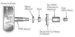
CAUTION: Any time a sensor is to be installed in a wheel, it is necessary to install a new sensor-to-wheel seal, metal washer and valve stem nut, to ensure airtight sealing (see Figure 1). CAUTION: DO NOT reuse the sensor-to-wheel grommet. Always use a new grommet when installing a pressure sensor and properly torque the sensor nut.
Removal
1) Remove the tire and wheel assembly from the vehicle.
2) Demount the tire from the wheel following the tire changer manufacturer’s instructions while paying special attention to the following to avoid damaging the pressure sensor:
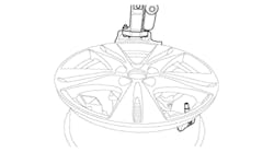
• When breaking the tire bead loose from the wheel rim, avoid using the bead breaker in the area of the sensor. That includes both front and rear beads of the tire (see Figure. 3).
• When preparing to demount the tire from the wheel, carefully insert the mounting/demounting tool at the valve stem +/- 10 degrees, then proceed to demount the tire from the wheel. Use this process on both the upper and lower tire beads.
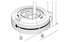
3) Using a thin-walled socket, remove the special nut retaining sensor to the wheel. While removing the nut, hold pressure against the rear of the metal valve stem to keep the valve stem from pushing rearward, which could damage the antenna strap (see Figure. 2).
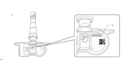
4) Remove the sensor from the wheel (see Figure 4).
Installation
NOTE: Before reinstalling an existing tire pressure sensor, replace the seal and metal washer at the base of the valve stem to ensure proper sealing (see Figure 1).
1) Wipe the area clean around the sensor/valve stem mounting hole in the wheel. Make sure the surface of the wheel is not damaged. CAUTION: To avoid damaging the sensor antenna strap, hold pressure against the rear of the metal valve stem while the sensor is inserted through the wheel mounting hole and the nut is installed (see Figures 2 and 4).
2) Insert the sensor through the wheel as shown keeping pressure against the rear of the metal valve stem. The potted side of the sensor is to be positioned toward the wheel.
Do not attempt to mount the sensor otherwise, or damage may occur. Install the sensor nut (with pressed-in washer) by hand (see Figures 4 and 5).
NOTE: Before tightening the sensor nut, push downward on the sensor housing in an attempt to make it flush with the interior contour of the wheel.
3) Using a thin-walled socket, install the sensor nut. While holding the sensor in position, tighten the sensor nut to 40 in.-lbs. (4.5 N.m).
CAUTION: Over-torquing the sensor nut by as little as 106 in.-lbs. (12 N.m) may result in sensor separation from the valve stem.
Under this condition, the sensor may still function; however, the condition should be corrected immediately.
4) Mount the tire on the wheel following the tire changer manufacturer’s instructions, paying special attention to the following to avoid damaging tire pressure sensor:
Rotating wheel tire changers
Once the wheel is mounted to the changer, position the sensor valve stem approximately 210 degrees from the head of the changer in a clockwise direction before rotating the wheel (also in a clockwise direction) to mount the tire. Use this procedure on both the upper and lower tire beads (see Figure 6).
Rotating tool tire changers
Position the wheel on the changer so that the sensor valve stem is approximately 210 degrees from the head of the changer in a clockwise direction from the mounting end of the tool (see Figure 7). Make sure the sensor is clear of the lower bead breaker area to avoid damaging the sensor when the breaker rises. Rotate the tool in a counterclockwise direction to mount the tire. Use this procedure on both the upper and lower tire beads.
5) Adjust air pressure to specification. Make sure the original style valve stem cap is securely installed to keep moisture out of the sensor. Install the wheel and tire assembly on the vehicle.
6) Drive the vehicle for a minimum of 5 minutes while maintaining a continuous speed above 15 mph (24 km/h). During this time, the system will learn the new sensor ID code and will clear any DTCs automatically. If a sensor cannot be trained, see the appropriate manufacturer service information. ■
Torque specifications
Component Ft.-lbs. (N.m)
Wheel nut 85 (115)
In.-lbs. (N.m)
Tire pressure sensor nut 40 (4.5)
Over-torquing the sensor nut by as little as 106 in.-lbs. (12 N.m) may result in sensor separation from the valve stem. Under this condition, the sensor may still function; however, the condition should be corrected immediately.
Information for this column comes from the tire pressure monitoring systems data in ProDemand®, Mitchell 1’s auto repair information software for domestic and import vehicles. Headquartered in Poway, Calif., Mitchell 1 has provided quality repair information solutions to the automotive industry since 1918. For more information, visit www.mitchell1.com.


