SUBJECT VEHICLES: 2014-2016 Chrysler/Dodge Dart
RELEARN PROCEDURE? Yes.
SPECIAL TOOLS NEEDED? Yes, a TPMS-RKE analyzer (9936) with a scan tool.
The tire pressure monitoring system (TPMS) in 2014-2016 Chrysler/Dodge Darts monitors air pressure in the four road tires (excludes spare). Pressure in the spare tire is monitored in case of a matching spare with sensor. Sensor transmissions occur if there is a significant change in pressure.
A radio frequency hub module (RFHM) has to be awake when the sensor transmits to monitor spare pressure. The TPMS consists of tire pressure monitoring sensors attached to each road wheel through the valve stem mounting hole, an electronic display, and an indicator lamp. The system communicates through the RFHM. Upon detection of a warning or fault condition, the RF hub will send a request to the module that controls the indicator lamp and the text display via the vehicle bus system to illuminate or flash the indicator lamp.
Also, upon detection of a warning or fault condition, the electronic display will send a request to sound the “chime.” The RF hub will store all wheel sensor IDs and locations and faults in memory that can be accessed through diagnostic communication. All other data values transmitted from each active wheel sensor shall be stored in the RF hub memory.
The RF hub automatically learns and stores the sensor IDs while driving within 20 minutes continuously above 20 mph (32 km/h) after a sensor has been replaced. The learning sequence will initiate when the vehicle has been stopped for more than 20 minutes. NOTE: A new sensor ID can also be programmed directly into the RF hub by using a RKE-TPMS analyzer in conjunction with a scan tool. Once the new sensor ID has been programmed, the RKE-TPMS analyzer can be used to update the TPMS by activating the sensor.
If the TPMS detects the tire pressure in any road tire is low, beyond the low pressure (lamp) ON threshold (see placard table), the TPMS will continuously illuminate an indicator lamp.
If a system fault is detected, the indicator lamp will flash on/off for 75 seconds, and then remain on solid.
If the RF hub detects a warning or fault condition at ignition key “on,” the display module will request a chime once per ignition cycle for the first “warning” or “fault” condition detected. A “warning” or “fault” condition will remain enabled until the problem causing the condition is corrected and removed/reset.
If a system fault is detected, a chime will sound, and the TPMS indicator (telltale) lamp will flash for 75 seconds, and then remain on solid.
For vehicles with the premium TPMS, a “CHECK TPM SYSTEM” message will appear in the electronic vehicle information center (EVIC), followed by a graphic display.
A system fault can occur by many scenarios, including the following:
- Signal interference due to electronic devices or driving next to facilities emitting the same radio frequencies as the TPMS sensors.
- Installing some form of aftermarket window tinting that affects radio wave signals.
- Accumulation of snow or ice around the wheels or wheel housings.
- Using tire chains on the vehicle.
- Using wheels not equipped with TPMS sensors.
Reset procedures
TPMS indicator
Check air pressure as necessary in all tires using a known accurate air gauge and adjust to the specification listed on the tire inflation pressure label (placard) provided with the vehicle (usually applied to the driver side B-pillar). While adjusting air pressure (with key ON to keep RFHM active) in a tire on the vehicle, allow approximately two minutes for the message or indicator lamp to go out. (The vehicle may need to be driven for pressure to update.)
TPMS sensors
NOTE: A new sensor ID can be programmed directly into the RF hub by using a RKE-TPMS analyzer in conjunction with a scan tool. Once the new sensor ID has been programmed, the RKE-TPMS analyzer can be used to update the TPMS by activating the sensor.
The battery-operated TPMS is both a transmitter and a receiver. The TPMS sensor can be forced to transmit if using a special tool such as a TPMS-RKE analyzer. The TPMS-RKE analyzer has the ability to change the sensor mode and to diagnose a faulty TPMS sensor. Using a TPMS-RKE analyzer can take up to a minute to force a transmission from a sensor.
Each sensor’s transmitter broadcast is uniquely coded so that the module can monitor the state of each of the sensors on the four rotating road wheels. The module can automatically learn and store the sensor’s ID while driving within 20 minutes continuously above 20 mph (32 Km/h) after a sensor has been replaced. The vehicle must be stationary for more than 20 minutes in order to initiate the learning sequence. The sensor IDs also can be programmed using the TPMS-RKE analyzer tool. Scan each TPMS sensor at each road wheel, and store each sensor ID in the correct location (left front, left rear, right front and right rear). Connect the TPMS-RKE analyzer tool to the scan tool.
Then follow the programming steps outlined in the diagnostic scan tool for “Program Tire Pressure Sensor ID w/ TPM Tool.”
Demounting/mounting procedures
CAUTION: The TPMS has been optimized for the original equipment tires and wheels. TPMS pressures have been established for the tire size equipped on the vehicle. Undesirable system operation or sensor damage may result when using replacement equipment that is not of the same size, type or style. Aftermarket wheels can cause sensor damage. Do not use aftermarket tire sealants or balance beads if the vehicle is equipped with TPMS, as damage to the sensors may result.
CAUTION: Tire pressure sensor valve stem caps and cores are specially designed for the sensors. Due to risk of corrosion, do not use a standard valve stem cap or core in a tire pressure sensor in place of the original equipment style sensor cap and core. Any time a sensor is to be installed in a wheel, it is necessary to install a new sensor-to-wheel seal, metal washer and valve stem nut, to ensure air tight sealing.
CAUTION: When installing the valve core, be sure to tighten the core to specifications. Over-tightening by as little as three or four inch pounds can damage the sensor.
Sensor removal
NOTE: The tire pressure sensor, the valve stem, and all valve stem components including the cap and the valve core can be serviced and replaced individually.
NOTE: When demounting or mounting the tire on the wheel, follow the tire changer manufacturer’s instructions while paying special attention to avoid damaging the pressure sensor.
NOTE: Replace the valve stem assembly with each tire change or when the tire is removed from the wheel. Install a NEW valve stem and valve stem core if they are removed from the wheel or valve stem.
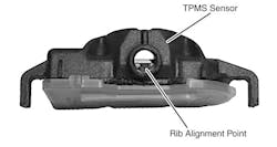
1) To remove the sensor from the valve stem, press down on the spring clip using a small screwdriver while pulling (see Figure 1).
2) Remove the valve stem from the wheel.
Sensor installation
CAUTION: Any time a sensor is to be reinstalled in a wheel, a new valve stem assembly must be installed to ensure air tight sealing. NOTE: When installing a new valve stem, do not install it with the sensor attached. If it is a new sensor, separate the valve stem from the sensor first and then install the components separately.
NOTE: Replace the valve stem assembly with each tire change or when the tire is removed from the wheel.
NOTE: When installing a new valve stem, water or water/soap solution should be used for proper installation into the wheel.
1) Wipe the area clean around the sensor/valve stem mounting hole in the wheel. Make sure the surface of the wheel is not damaged.
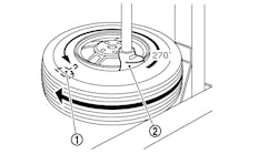
2) Position the valve stem into the wheel mounting hole with the rib at the 12 o’clock position to the wheel, and then pull it through to seat it with a standard valve stem installation tool (see Figure 2).
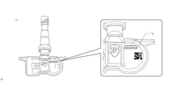
NOTE: The valve stem has two notches on the locking pin where the sensor can be installed depending on the thickness of the rim on the wheel (see Figure 4 on page 71). Refer to steps 4 and 5 for installation on both types of wheels. The sensor is properly installed if the sensor is as close as possible to the valve and the locking pin is visible past the spring clip.
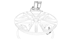
3) Install the sensor onto the valve stem by aligning the rib in the sensor to the valve stem (see Figure 3).
NOTE: The valve stem locking pin will be slightly visible after installation.
4) For a wheel with a thick rim, use the first locking pin notch (first from the tip on the locking pin). Push down on the spring clip using a small screwdriver and slide the sensor up until it stops against the bottom part of the valve. Gently pull down to verify the spring clip has engaged (see Figure 5).
NOTE: The locking pin will be highly visible after installation.
5) For a wheel with a thin rim, use the second locking pin notch. Push down the spring clip using a small screwdriver and slide the sensor up until it stops against the bottom part of the valve (see Figure 6). Gently pull down to verify the spring clip has engaged.
6) Mount the tire on the wheel and install the tire and wheel assembly on the vehicle.
7) Adjust air pressure to that listed on the tire inflation pressure label (placard) provided with the vehicle (usually applied to driver’s side B-pillar).
Make sure an original style valve stem cap is securely installed to keep moisture out of the sensor.
8) Perform one of the following to make the system learn the new sensor ID:
a. Once the vehicle has remained stationary for more than 20 minutes, drive the vehicle for a minimum of 20 minutes while maintaining a continuous speed above 20 mph (32 km/h). During this time, the system will learn the new sensor identification. This is part of the TPMS diagnostic verification test. B. Use the TPMS-RKE analyzer (9936) with the scan tool to program the RF hub module with the tire pressure sensor ID. This is part of the TPMS diagnostic verification test.
9) If a sensor cannot be trained, refer to the appropriate diagnostic information. ■
Torque specifications
Component Ft.-lbs. (N.m)
Wheel nut 100 (135)
Headquartered in Poway, Calif., Mitchell 1 has provided quality repair information solutions to the automotive industry for more than 80 years. For more information, visit www.mitchell1.com.
To see more TPMS columns, click:
Volkswagen Rabbit, Golf, GLI, GTI, Jetta and R32


